
 Español


A technician pulls a weeping fitting off a hydraulic power unit, matches it against a catalog photo, and orders what looks identical. The replacement threads on, the system runs, and the joint starts leaking again within a shift. In most of these cases the problem was never part quality — it was that nobody actually measured the original fitting before ordering.
Here is the conclusion up front: measuring a JIC fitting correctly takes three checks — thread diameter, threads per inch, and the 37-degree flare angle. Diameter and pitch together give you the dash size, which is how JIC fittings are specified and ordered. The flare angle check confirms the fitting really is JIC and not a lookalike. This guide walks through each check with the tools, numbers, and reference data you need to get the replacement right the first time.
What You Are Actually Measuring on a JIC Fitting
JIC stands for Joint Industry Council. Fittings in this family follow the SAE J514 standard and are defined by two features: a 37-degree flared seat and a straight (parallel) UNF thread. The seal is made metal-to-metal where the flared tube end or fitting nose seats against the mating cone — no O-ring, no tape, no sealant in the joint.
Two points cause most sizing confusion. First, the dash size that names the fitting (such as -4 or -8) refers to tube outside diameter in sixteenths of an inch, not to the thread itself. A -4 JIC fitting carries 7/16-inch threads. Second, JIC fittings are not ferrule-type compression fittings; those grip the tube with ferrules and have an entirely different geometry. If the part on your bench has one or two ferrules and no flare cone, the sizing logic in this article does not apply — you would instead follow the identification approach covered in our comparison of single and double ferrule fitting types.
The Tools That Make the Measurement Reliable
A tape measure will not do this job. On small fittings, adjacent dash sizes differ by roughly 1.5 millimeters of thread diameter, which is well inside the error band of eyeballing. Use the following instead:
- Digital or dial calipers, readable to at least 0.01 inch (0.25 mm)
- A thread pitch gauge covering 12 to 28 threads per inch
- A flare angle gauge, or a known JIC fitting to use as a physical reference
- A JIC thread identification chart for converting readings into dash sizes
Remove the fitting from the machine before measuring whenever possible. Measuring in place invites skewed caliper jaws and readings taken over the hex instead of over the threads.
Step 1: Determine Gender and Measure the Thread Diameter
Start by establishing whether you are holding a male fitting (external threads with a flared nose) or a female fitting (internal threads with a flared cup). The two are measured on opposite sides of the thread form.
Male JIC fittings
Close the caliper jaws over the threads and measure the outside diameter at the widest point — crest to crest across the thread peaks. Keep the jaws perpendicular to the fitting axis; a tilted caliper reads large. A male -4 measures about 0.44 inch (11.1 mm) over the threads, and a male -8 measures 0.75 inch (19 mm). Take two or three readings at slightly rotated positions, especially on a worn fitting, and work with the average.
Female JIC fittings
Open the caliper jaws inside the threaded bore and measure the inside diameter at the broadest point, again keeping the tool square to the axis. The female reading will always come out smaller than the male OD it mates with — the female half of a -4 pair reads noticeably under 7/16 inch. Do not force the female ID to match a male thread value on the chart; record the ID and pitch, then confirm the pairing with the reference table below.
Step 2: Count the Threads per Inch
JIC fittings use Unified Fine (UNF) threads, so the pitch is fine and consistent: a -4 has 20 threads per inch, a -6 has 18, a -8 has 16, and sizes from -12 upward drop to 12 threads per inch. Fan a thread pitch gauge against the threads until one leaf seats with no rocking, then read the pitch off the leaf.
The pitch check also reveals thread type. JIC threads are straight and run parallel from end to end. If the thread tapers and tightens as it goes, you are looking at NPT pipe thread rather than JIC, and no amount of re-measuring will make the two families interchangeable.
Step 3: Match Your Measurements to a Dash Size
With diameter and pitch in hand, match them against the standard JIC thread series. The dash size equals the tube outside diameter in 1/16-inch units — a -8 runs 1/2-inch tube with 3/4-inch threads — so the same table also tells you what tubing the fitting was built for.
| Dash Size | Tube OD (inch) | Thread Size (UNF) | Male Thread OD (inch) | Threads per Inch |
|---|---|---|---|---|
| -2 | 1/8 | 5/16-24 | 0.31 | 24 |
| -3 | 3/16 | 3/8-24 | 0.38 | 24 |
| -4 | 1/4 | 7/16-20 | 0.44 | 20 |
| -5 | 5/16 | 1/2-20 | 0.50 | 20 |
| -6 | 3/8 | 9/16-18 | 0.56 | 18 |
| -8 | 1/2 | 3/4-16 | 0.75 | 16 |
| -10 | 5/8 | 7/8-14 | 0.88 | 14 |
| -12 | 3/4 | 1-1/16-12 | 1.06 | 12 |
| -16 | 1 | 1-5/16-12 | 1.31 | 12 |
| -20 | 1-1/4 | 1-5/8-12 | 1.63 | 12 |
| -24 | 1-1/2 | 1-7/8-12 | 1.88 | 12 |
Readings within a few thousandths of a chart value are normal manufacturing tolerance. Readings that sit between two sizes usually mean the threads are worn, damaged, or simply not JIC. When the numbers refuse to match, move on to the flare check — the angle often reveals what the threads are hiding.
Step 4: Verify the 37-Degree Flare Angle
Thread measurements alone cannot separate a JIC fitting from a 45-degree SAE flare fitting, because the two look nearly identical on the bench and their thread dimensions on smaller sizes are close enough to invite a wrong match. The flare is what decides. JIC seats at 37 degrees; the general-purpose SAE flare seats at 45 degrees. Mated together, the two cones touch only on a narrow line — and that line is exactly where a hydraulic joint weeps.
The fastest verification is comparison: seat the nose of your fitting against a known JIC fitting of the same size. A true 37-degree pair nests flush with full metal contact, while a 45-degree fitting rocks on its edge. A flare angle gauge or a bluing check on the cone gives the same answer with more precision. Once the angle confirms JIC and you need new male ends for flared tube assemblies, a stainless steel flared fitting male connector built to the 37-degree seat is the direct replacement to source.
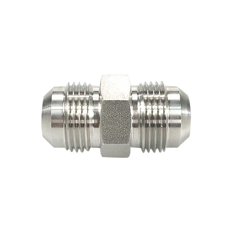 Stainless Steel Flared Fitting Male Connector with 37-Degree JIC SeatOnce a flare angle check confirms a fitting is true JIC, this stainless steel male connector offers a direct replacement for flared tube assemblies. Its flared design promotes a tight seal in hydraulic and pneumatic pipelines.View Product →
JIC, NPT, and the Adapter Question
Another frequent trap is measuring a fitting that is only partly JIC. Many hydraulic assemblies combine a 37-degree JIC swivel on one end with an NPT pipe thread on the other. If your caliper shows a tapered thread that tightens along its length, you are looking at the NPT half, and it must be identified by nominal pipe size rather than by the JIC chart.
That mixed construction is exactly why JIC-to-NPT transition fittings exist. When a pump or valve port is NPT and the hose end or tubing run is JIC, the correct part is an adapter rather than a straight replacement. Size the JIC side with the table above and the pipe side by its NPT designation, and a stainless steel SAE 37 degree JIC to NPT male hydraulic tube adapter joins the two standards without compromising the flare seal.
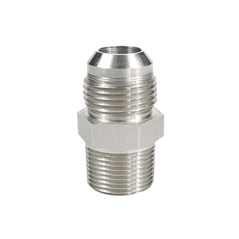 Stainless Steel SAE 37 Degree JIC to NPT Male Hydraulic Tube AdapterWhen an NPT pump or valve port must connect to a JIC hose end, this stainless steel adapter joins the two thread standards. The 37-degree flare side and NPT male side keep a leak-proof seal under pressure.View Product →
Getting the Measurement to Survive Purchasing
A correct bench measurement only pays off if it survives the ordering process. A few habits drawn from hydraulic maintenance practice make the difference:
- Measure before removal whenever the joint allows, and photograph the fitting next to a ruler or tag for the purchase order.
- Record three values, not one: thread diameter, threads per inch, and flare angle. A single number invites substitution errors.
- Keep the old fitting as a physical sample for the supplier to verify against, especially at -12 and larger, where a mixed-up order is costly to return.
- Confirm material and pressure class alongside size; a correctly measured carbon steel fitting dropped into a stainless line is still the wrong part.
Where a line transitions from a flare seat into an NPT port on the female side, the female-threaded flared adapter family solves it the same way as the male version above, just from the opposite direction. And if the rest of the circuit uses ferrule-style ends instead of flares, it is worth reviewing how single ferrule hydraulic fittings are specified and assembled before mixing any of these standards in one run.
Measured this way — diameter, pitch, and angle, checked in that order — a JIC fitting can be identified and ordered with confidence on the first attempt, and the joint goes back together dry.
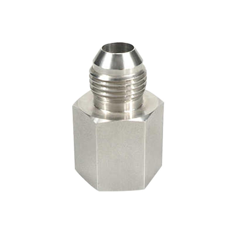 Stainless Steel NPT Female to Flared Male Tube Fitting AdapterWith JIC diameter, thread pitch, and flare angle verified, this adapter suits setups needing an NPT female thread joined to a flared male tube end. Its stainless construction fits hydraulic, pneumatic, and process pipeline applications.View Product →