
 Español



A quarter turn is all it takes to operate a ball valve, which is why so many of them are fitted on a Friday afternoon and then forgotten for years. Yet most of the complaints we hear — a handle that will not budge two seasons later, a drip at the threads, a tube connection that weeps only when the line is cold — begin on the day of installation rather than in service. The steps below are the ones our own technicians follow when they build and test stainless steel ball valve assemblies, and they apply whether you are threading a valve onto a manifold or making up a tube joint on an instrument line.
Before You Start: Isolation, Tools, and a Clean Work Area
Start by taking the energy out of the system, not by reaching for a wrench. Close the isolation valve upstream, lock it out if your site requires it, drain the line, and confirm with a gauge that the pressure has actually gone. A closed ball valve still traps fluid between its seat and the next valve in line, so slack off the joint slowly and let that trapped volume escape before you open anything fully. Hot media and residual chemical need time to cool and to be flushed.
The tool list is short, and nothing on it is expensive:
- Two wrenches sized to the valve body and to the fitting — one adjustable wrench doing both jobs is how bodies get twisted
- A square tube cutter, plus a deburring tool or fine file
- Thread sealant or PTFE tape rated for the medium, and a caliper to confirm tube outside diameter
- A torque wrench for ferrule and flange work, where the maker gives a value
- Gloves, eye protection, and a container for the drained fluid
Skipping the caliper or the second wrench is where most trouble begins. A tube that measures 3/8 inch on the outside is not automatically the tube the fitting was designed for, and a valve body twisted against a rigid pipe will leak at the stem long before the seat ever wears out.
Read the Valve Before You Read the Pipework
Most stainless ball valves carry their size, body material and pressure class on the body or on a tag. Compare those markings with the line you are joining: a valve rated for 1000 psi on a 1500 psi hydraulic circuit is the wrong valve no matter how well it is installed. Temperature matters just as much, because the allowable pressure drops as the temperature rises, and steam service derates a standard PTFE seat far below its room-temperature rating.
Then check three physical details. First, the port: full-port valves pass a pig or a viscous medium with almost no pressure loss, while reduced-port valves are shorter and cheaper but restrict flow. Second, the flow path — ordinary two-way ball valves are bidirectional, but three-way valves, diverting designs and some specialty bodies are not, and an arrow on the body is there for a reason. Third, handle clearance: the lever needs a clean 90 degrees of travel, room for a hand or an actuator, and a position that will not collect water or foul against a wall, a beam or adjacent tubing. If you are still deciding which body style suits the duty, our overview of how a ball valve works and how to choose one covers the trade-offs in more detail.
The Connection Decides the Procedure
Once the valve is on the bench and confirmed, the installation method follows the joint type rather than the valve itself. The four styles we supply most often each fail in their own way, and each has one detail that matters more than everything else.
| Connection | Typical service | Preparation | The detail that matters |
|---|---|---|---|
| Female NPT / BSPT threaded | Instrument air, hydraulic power units, general process lines | Sealant on male threads only, first two threads left bare | Correct engagement — hand-tight plus one to two turns, with the body backed up by a second wrench |
| Double ferrule compression | Impulse, analyzer and instrumentation tubing | Square cut, deburred tube; nut marked at finger-tight | Exact make-up turns from finger-tight, and new ferrules every time |
| 37 degree flare (JIC / SAE) | Hydraulic and mobile equipment lines | Clean, uncracked flare cone matched to the valve seat | Metal-to-metal cone contact; no sealant anywhere near the flare face |
| Butt weld | High-purity, high-pressure or leak-critical service | TIG preparation, purge plan, weld map | Weld quality and post-weld cleaning or passivation |
Step by Step: Installing the Valve
- Measure and cut. Mark the cut with the valve, nuts and any union in place, so the finished assembly is not short by a ferrule length. Cut square — an angled cut will never seat properly under a ferrule.
- Prepare the end. Deburr the outside and inside of the tube, wipe it clean, and inspect for scratches or ovality. For threaded ends, clean the male thread and apply tape or sealant clockwise, leaving the first two threads bare so nothing is pushed into the bore.
- Support the pipe. Bring the pipe ends into alignment before anything is tightened. A valve forced into a misaligned line is preloaded from day one, and that load ends up on the stem seal.
- Position the valve. Confirm the arrow direction, set the handle where it can be reached and fully swung, and leave space for future actuation. On insulated lines, keep the handle and the stem above the insulation.
- Make up the joint. Run the nut or thread hand-tight, then finish with a wrench while a second wrench holds the valve body steady. This is the single most effective habit for protecting the body and the tube.
- Follow the ferrule table. For stainless double ferrule fittings, finger-tight plus roughly one and a quarter turns is typical for the 1/4 to 1 inch range, with different values for smaller and larger sizes. Mark the nut before you start so the turns are counted, not estimated.
- Cycle the valve. Open and close it two or three times while the system is still unpressurised, so you know the handle travel is clear and nothing is binding against the pipework.
- Pressure test before start-up. Never commission a new joint on the assumption that it looks right.
If you are building instrument assemblies rather than repairing one joint, our instrument ball valve range covers threaded, ferrule and three-way bodies that are made up the same way described here.
Tightening: Where Most Leaks Begin
Threaded joints fail in two opposite directions. Under-tightening leaves too few threads engaged and the joint works loose under vibration; over-tightening cracks female threads or distorts the body, and on a stainless valve it can also gall the thread so badly that the joint never comes apart again. Tighten until roughly one or two threads remain visible, then stop. If a joint still drips at that point, add sealant rather than torque.
For tube connections, the ferrule does the sealing and the nut only drives it. A ferrule that has been swaged cannot be reused: cut the tube back past the deformed section and start again with a new ferrule and nut. Over-tightening crushes the tube and can crack it just behind the ferrule, which is a failure that often shows up weeks later rather than on the day of the test.
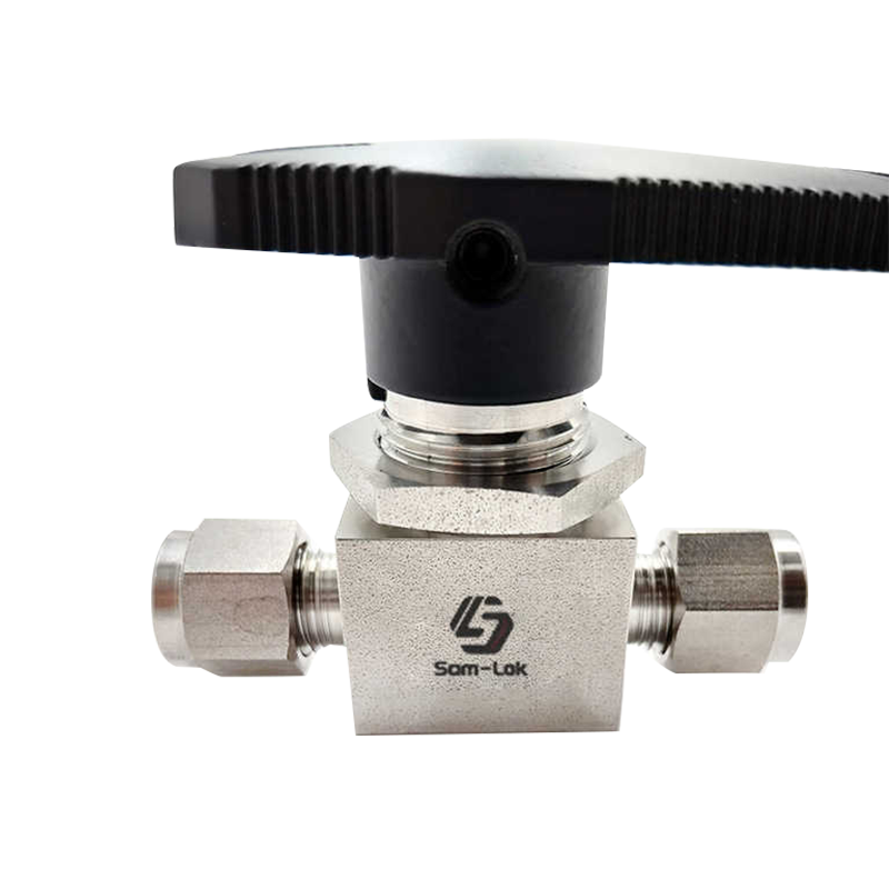 Stainless Steel Double Ferrule Ball ValveFor high-pressure tube connections, this ball valve offers precise flow control, a one-piece body, and top-entry inspection and repair.View Product →
The same logic applies to threaded stainless bodies, where a clean thread and correct engagement do more for leak-tightness than any amount of force.
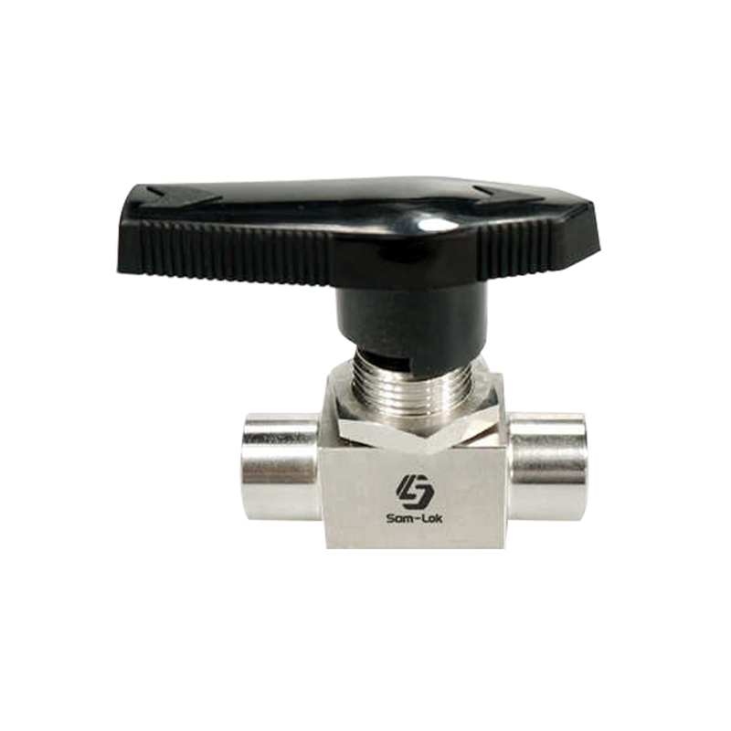 Stainless Steel Female NPT Thread Ball ValveFor threaded stainless connections, this corrosion-resistant valve combines NPT sealing with smooth ball flow control and top-entry servicing.View Product →
High-pressure hydraulic valves add one more consideration: the torque values are higher, the consequences of a loose joint are greater, and the body is usually heavier, so it must be supported rather than left hanging on the pipe thread alone.
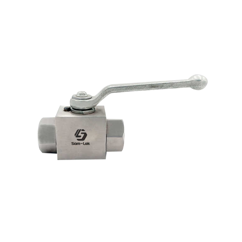 Stainless Steel Female Thread High Pressure BKH Ball ValveReview this BKH stainless ball valve for high-pressure oil and gas lines requiring reliable sealing and quick, stable flow control.View Product →
Testing and Commissioning
Hydrostatic testing with water is the safer default, carried out at 1.5 times the design pressure or to whatever local code specifies, with air removed from the line. Pneumatic testing stores a great deal of energy and should only be done where the procedure allows it and with proper standoff. For gas service, leak detection means a soap solution or an electronic detector, never a flame.
During the test, watch both the joint and the stem, and cycle the valve closed and open once under pressure to confirm the seat seals in both directions. After a water test, drain and dry stainless lines properly — water left standing in a crevice is exactly where chloride pitting starts.
Mistakes We See Most Often
- Installing against a misaligned pipe and calling the resulting stem leak a manufacturing fault
- Counting ferrule turns by feel instead of marking the nut
- Wrapping tape all the way to the end of a male thread and pushing fragments into the bore
- Using a ball valve as a throttling valve — a half-open ball erodes its seat quickly
- Leaving the handle pointing downward, where it collects water and cannot be reached
- Testing with air on a line that was designed for a hydrostatic test
Keeping It Working
Exercise every ball valve a full quarter turn once a quarter, even the ones that are normally open or normally closed. That single habit prevents most seized handles, because it keeps the seat from taking a permanent set in one position. Support long runs so the valve is not the only thing holding the pipe, and replace seats or stem packing with the maker's kit rather than improvising. When a body corrodes, the handle sticks after exercising, or the stem drips between turns, replacement is usually cheaper than repair.
Questions We Get Asked
Does a ball valve have to be installed in a particular direction?
Two-way ball valves are normally bidirectional and can be fitted either way. Three-way, diverting and some specialty bodies are not, so follow the arrow on the body. If there is no arrow and the valve has more than two ports, check the data sheet before cutting anything.
Should the handle point up?
Up or horizontally is fine as long as the lever has a clear 90 degrees of swing and can be reached. Downward-facing handles trap water and debris and are hard to operate in a hurry, so avoid them where you have a choice.
How many turns does a double ferrule nut need?
For stainless double ferrule fittings in the 1/4 to 1 inch range, one and a quarter turns past finger-tight is a common figure, with larger sizes and different makers varying. Use the manufacturer's make-up table and mark the nut so the turns are counted.
Can a ball valve be installed on a vertical pipe?
Yes. Support the weight of the valve and the pipe above it so the joint is not carrying the load, and keep the handle within reach of whoever will operate it.
Installing a ball valve well is less about technique than about sequence: isolate properly, confirm the valve suits the line, prepare the end before you tighten anything, count your turns, and test before you hand the system back. Everything after that is maintenance, and a valve that was installed correctly tends to need very little of it.
