
 Español


A valve reduces flow rate by adding resistance to the path of the fluid. Liquid or gas only moves because a pressure difference exists between two points, and a partly closed valve takes a share of that difference for itself. What the valve consumes is no longer available to push fluid through the rest of the line, so flow settles at a lower value. That is the whole mechanism in one sentence.
The useful detail lies in how much pressure a valve claims, how the trim shape changes that claim as the valve moves, and what happens to the rest of the system while the flow drops. We have supplied stainless steel valves and fittings to instrument, hydraulic and general industrial lines for over a decade, and the questions customers ask about throttling follow a very familiar pattern. Here it is.
What Happens Inside a Partly Closed Valve
The restriction is created by the trim: a needle, plug, disc or ball moving toward its seat. Closing the valve narrows the open area, and two effects follow.
- The fluid speeds up. Continuity demands that the same mass pass through a smaller area, so velocity rises in the throat and, by Bernoulli's principle, the local static pressure falls.
- Energy is lost downstream. The accelerated fluid never fully recovers its pressure. Turbulence and friction in the wake of the restriction turn mechanical energy into heat, which the fluid carries away.
That second effect is what really matters. A valve is not a plug that simply blocks a pipe; it converts pressure energy into an irreversible loss. The larger that loss grows, the less pressure difference remains to drive flow, and the lower the flow rate becomes.
Pressure Drop Is the Currency That Buys Flow
Treat the pressure produced by a pump, a regulator or a gas header as a budget. Supply piping, filters, heat exchangers, valves and discharge pipework all spend part of it, and whatever is left over is what actually moves the fluid. Throttling increases the valve's share, the surplus shrinks, and flow falls until the books balance again.
Fixed supply pressure versus a pump
With a pressure regulator or a gas header upstream, the supply pressure holds roughly steady as you close the valve. The valve's own pressure drop rises, flow falls, and the sizing equation below describes the result.
With a centrifugal pump the picture changes. Throttling adds resistance and steepens the system curve, so the operating point slides along the pump curve toward higher discharge pressure and lower flow. The valve is steering the pump rather than acting alone. A pump throttled far back can run left of its best efficiency point, recirculate internally, run hotter and noisier, and wear its seals sooner.
The Numbers: Cv, Kv and the Square Root Rule
Valve capacity is expressed as a flow coefficient. In US units that is Cv, the gallons per minute of 60°F water that pass with a one psi drop across the valve. The metric equivalent is Kv. For a liquid:
Q = Cv × √(ΔP / SG)
where Q is flow, ΔP is the pressure drop across the valve and SG is the specific gravity of the liquid. Because Cv itself depends on valve position, the equation carries both effects at once: the opening changes Cv, and throttling changes ΔP.
The square root is what catches people out. Flow is not proportional to pressure drop but to its square root, so at a fixed opening, cutting the available pressure drop to a quarter halves the flow. The same mathematics explains why a small turn of the stem on a nearly closed valve changes flow so sharply: at low lift, a fractional change in open area produces a large percentage change in Cv.
Valve Characteristics: How Smoothly the Flow Falls
Two valves with the same capacity at full open can behave very differently at half open. The inherent characteristic describes how Cv grows with travel.
| Stem travel | Linear trim | Equal-percentage trim | Quick-opening trim |
|---|---|---|---|
| 10% | 10% | 3% | 50% |
| 30% | 30% | 7% | 85% |
| 50% | 50% | 14% | 100% |
| 70% | 70% | 31% | 100% |
| 100% | 100% | 100% | 100% |
Quick-opening trims reach most of their capacity in the first third of travel, which suits on/off duty. Equal-percentage trims give the widest controllable range and are the usual choice for control loops. Linear trims suit cases where the pressure drop across the valve stays fairly constant.
Installed behaviour never matches the published curve exactly, because ΔP across the valve changes as flow changes, which is one more reason equal-percentage trim is so common on throttled pump systems.
When Closing Further Stops Reducing Flow
There is a limit to what one valve can do. As liquid accelerates through the narrowest point just downstream of the seat, known as the vena contracta, its pressure can fall below the vapour pressure of the liquid. Bubbles form, and when they collapse further downstream they hammer the trim and the pipe wall. That is cavitation, and it announces itself with a rattling noise and a slowly eroding seat.
If the downstream pressure stays below the vapour pressure, the bubbles never collapse and the fluid leaves the valve partly vaporised. That is flashing, and it can ruin a valve in weeks. Gases have their own ceiling: once velocity in the throat reaches sonic speed the flow is choked, and lowering downstream pressure further changes nothing. The symptom is always the same. You keep closing the valve, the flow stops responding, and the noise grows.
The usual remedies are to split the pressure drop across two valves in series, specify anti-cavitation trim, or raise the downstream pressure.
Matching the Valve Type to the Job
Not every valve is built for throttling. Using an isolation valve to regulate flow is one of the most common mistakes we see, and it usually ends with a damaged seat and a puzzling loss of control.
| Valve type | Throttling behaviour | Typical role |
|---|---|---|
| Needle valve | Fine, repeatable adjustment over a small flow range | Instrument lines, sampling, low-flow regulation |
| Globe valve | Smooth, gradual change with good rangeability | General flow control and regulation |
| Ball valve | Little change until near closed, then abrupt | Isolation and on/off duty |
| Gate valve | Poor; gate and seat can be damaged | Isolation only |
| Butterfly valve | Moderate, and highly dependent on disc position | Large lines, general regulation |
| Check valve | Not adjustable; responds to flow direction | Preventing reverse flow |
Needle valves: the natural choice for fine reduction
A tapered needle moving into a small seat produces a long, gradual change in open area, which is why needle valves are the standard answer when flow has to be trimmed precisely and held there: sampling lines, purge flows, analyser feeds and low-flow circuits. Our guide to needle valve applications covers where they earn their place.
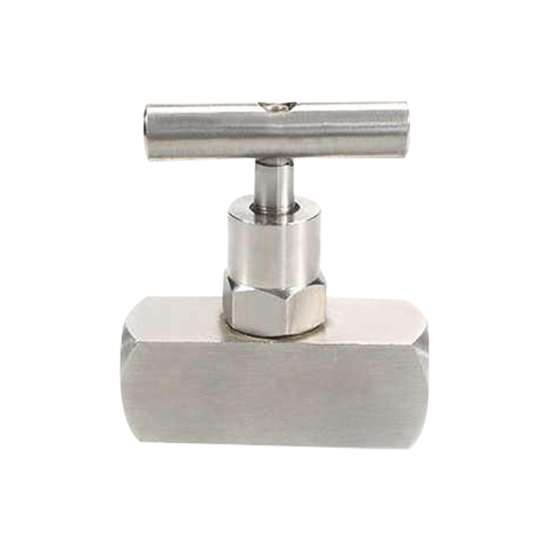 Stainless Steel Female Thread Needle ValveFor sampling lines and low-flow circuits, this stainless steel needle valve offers fine flow adjustment and a mirror-polished bore for stable regulation.View Product →
Ball valves: excellent isolation, poor throttling
A ball valve is happiest fully open or fully closed. Partly open, the flow path is awkward, the seat is exposed to high-velocity fluid, and the flow changes abruptly in the last few degrees of travel.
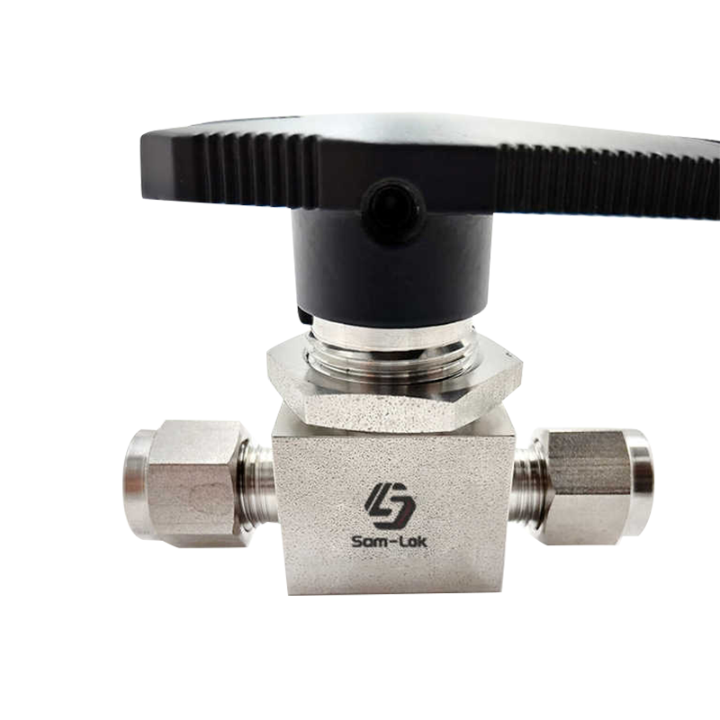 Stainless Steel Double Ferrule Ball ValveWhen flow must be fully opened or closed rather than throttled, this high-pressure instrument ball valve offers one-piece construction and top-entry serviceability.View Product →
Putting It to Work in Instrument and Hydraulic Circuits
In instrumentation, reducing flow is usually a small, local job: isolating a transmitter, venting a gauge, or trimming sample flow to an analyser. A two-way manifold with a needle valve gives you that adjustment and positive shut-off in a single assembly, which keeps the number of joints, and the number of potential leak paths, to a minimum.
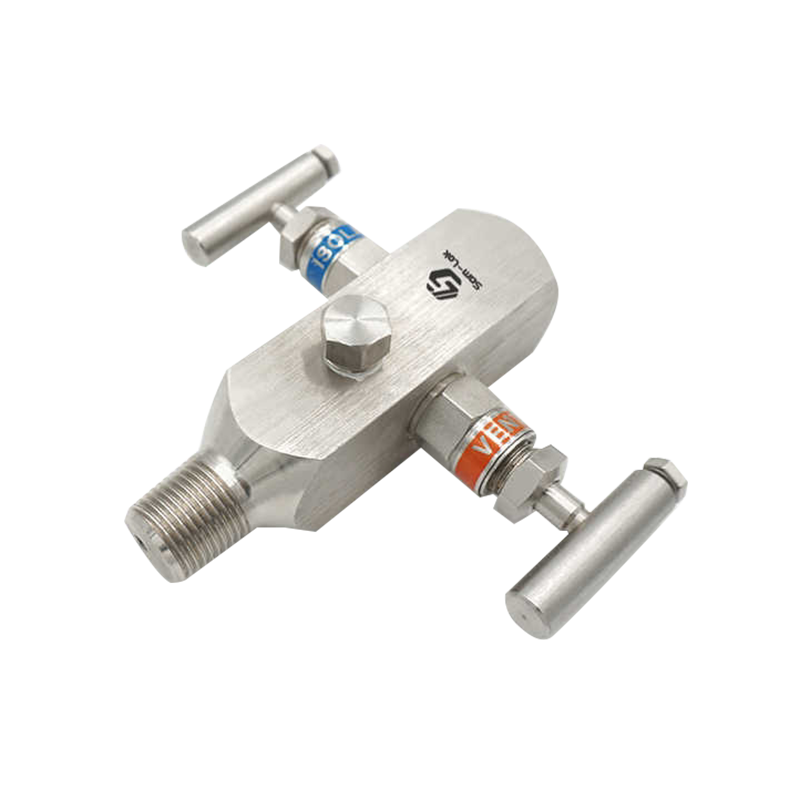 Stainless Steel Two-Way Valve Manifold Needle ValveFor instrumentation isolation and sample-flow trimming, this two-way manifold needle valve combines fine adjustment with shut-off in a single assembly.View Product →
In hydraulic circuits the principle is the same at much higher pressure, where erosion is a genuine risk and hardened trim, generous wall thickness and dependable sealing are worth the small extra cost.
A Practical Checklist for Reducing Flow
- Establish the flow you need at normal and minimum conditions, and the pressure available at each end of the circuit.
- Calculate the required Cv or Kv rather than guessing from the pipe size.
- Size the valve so normal operation falls between roughly 20 and 80 percent open, leaving room to adjust in both directions.
- Match the characteristic to the loop: equal percentage where the valve takes much of the pressure drop, linear where it does not.
- Keep isolation and throttling duties separate, and check for cavitation or choked flow whenever a large pressure drop happens in one step.
The Short Version
A valve decreases flow rate because it takes pressure away from the fluid and turns it into heat that is never recovered. Closing the valve increases its share of the available pressure difference, and what remains is no longer enough to sustain the original flow. How smoothly that happens depends on the trim; how far it can go depends on the fluid. If you are sizing a valve for a specific flow, we are glad to work through the numbers with you. Take a look at the fluid system solutions we build, or simply send us your line conditions and let us size it together.
