
 Español



Designing a flow control valve is rarely a matter of picking a standard product from a catalog and hoping it fits. It is a systematic process that starts with understanding your fluid system and ends with a valve that delivers stable, repeatable performance over years of service. Whether you are working on an instrumentation panel, a hydraulic power unit, or a chemical processing skid, the decisions made during the design phase determine how well the valve controls flow, how long it lasts, and how safely it operates.
As a manufacturer of industrial valves and fittings with more than a decade of hands-on experience, we have helped engineering teams and procurement professionals across Europe, North America, Asia, and the Middle East turn rough requirements into dependable flow control solutions. In this guide, we walk through the practical steps of designing a flow control valve — from defining system parameters to testing and validation.
Define Your System Parameters First
Every successful valve design starts with a clear picture of the operating environment. Skipping this step is the most common reason valves fail early or perform poorly. Before anything else, document the following:
- Fluid type and phase — liquid, gas, steam, or mixed media
- Working pressure range, including transient spikes
- Process temperature, both normal and upset conditions
- Required flow rate and the degree of regulation needed
- Acceptable pressure drop across the valve
- Frequency of operation and expected service life
- Media cleanliness, viscosity, and corrosiveness
| Parameter | Why It Matters |
|---|---|
| Fluid type | Determines material compatibility and seal selection |
| Pressure range | Defines body rating and seat sealing force |
| Temperature | Affects elastomer choice and thermal expansion behavior |
| Flow rate | Sets the required Cv value and valve size |
| Duty cycle | Influences wear rate and maintenance intervals |
Once these parameters are locked in, you can move on to selecting the right valve architecture.
Select the Right Valve Type for Flow Control
The term "flow control valve" encompasses several designs, and choosing among them depends on how precisely you need to regulate flow and how the valve will be operated.
Needle Valves for Fine Regulation
Needle valves are the workhorses of precise flow regulation. Their long, tapered needle and matching seat create a variable orifice that responds smoothly to small stem movements, making them ideal for instrumentation lines, sampling systems, and metering applications. When designing a needle valve for your system, pay attention to stem thread pitch and seat geometry, because these elements define the resolution of flow adjustment. Our general utility service needle valve is a practical example of a design that balances fine control with durability across a wide range of services. For a deeper look at where needle valves fit in a plant, see this guide to needle valve applications.
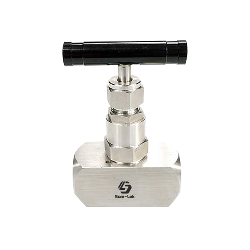 Stainless Steel General Utility Needle ValveThis stainless steel needle valve balances fine flow control with durability, offering pressures up to 10000 psi and a mirror-polished cone for smooth regulation across water, oil, gas, and acid services.View Product →
Ball Valves for Reliable Shutoff and Modest Throttling
Ball valves are prized for their low torque, quick operation, and tight sealing. In flow control service, a ball valve is usually chosen when the main requirement is reliable shutoff with occasional throttling. The bore profile and ball port shape can be modified to improve flow characteristics, but for sustained precision control, a needle valve or a characterized ball design is more appropriate. Our
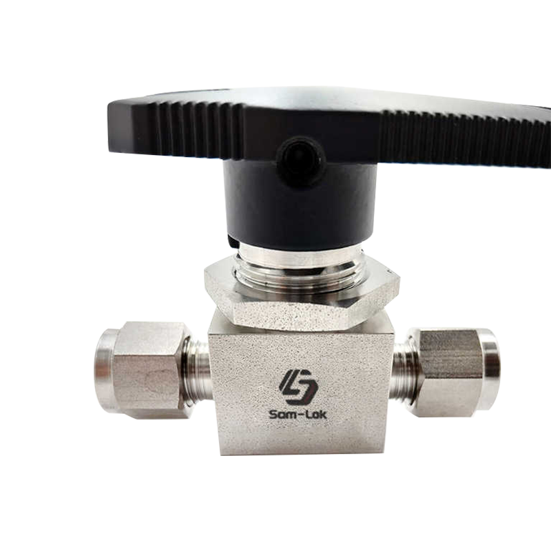 Double Ferrule Ball Valve for Instrumentation LinesA compact high-pressure ball valve with double ferrule connections, engineered for leak-tight shutoff and precise control in small-bore systems, with sizes down to 1/16 inch.View Product →
double ferrule ball valve is built for instrumentation and small-bore lines where compactness and leak-tight performance matter.
Check Valves for Backflow Prevention
If the goal is to prevent reverse flow rather than regulate flow rate, a check valve is the right architecture. Spring-loaded designs offer fast response, while swing-type check valves suit larger lines and lower velocity services. Our stainless steel check valve line covers threaded connections for compact installation in general service.
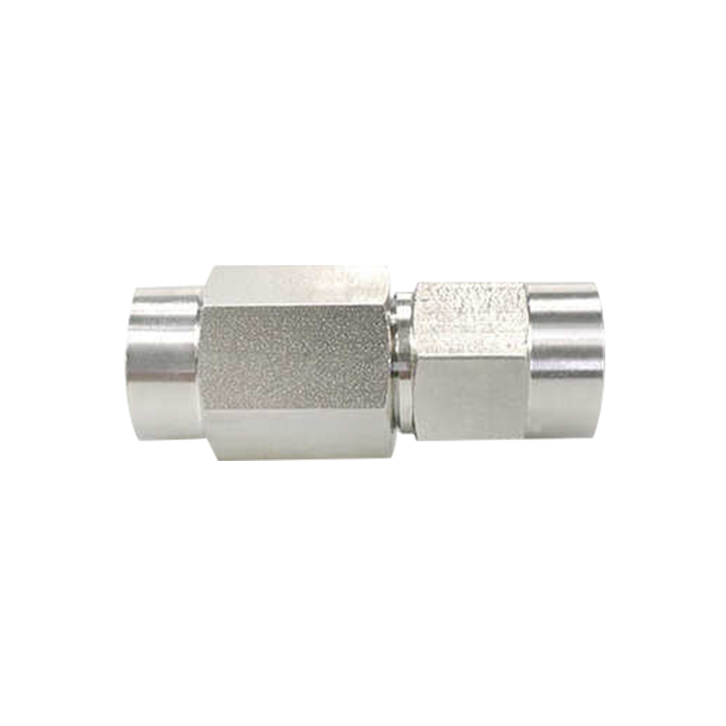 Stainless Steel Female Thread Check ValveThis check valve prevents reverse flow in corrosive and high-temperature services, featuring a female threaded connection and stainless steel body for compact, durable installation in industrial fluid systems.View Product →
Size the Valve Using the Flow Coefficient
The flow coefficient, commonly expressed as Cv, is the fundamental basis for sizing a flow control valve. Cv represents the number of US gallons per minute of water that will flow through a fully open valve with a pressure drop of 1 psi. For other fluids and conditions, the required Cv is estimated using the standard flow equation:
- For liquids: Cv = Q × √(SG / ΔP)
- For gases: add compressibility factors and upstream/downstream pressure corrections
- Always build in a safety margin of 20–30% above the calculated Cv
The calculated Cv helps you choose the correct valve size from the manufacturer's published Cv table. Undersizing restricts flow and causes excessive pressure drop; oversizing leads to poor control resolution at low flow rates and potential cavitation or noise.
Match Materials to the Service Environment
Material selection is where theory meets real-world reliability. The valve body, trim, seat, and seals must withstand the fluid's chemical nature, the pressure, and the temperature over the valve's full service life.
- Body material: 316 stainless steel is the default for corrosive and high-purity services; 304 offers a cost-effective alternative in milder conditions; carbon steel with plating suits hydraulic fluid.
- Seat and seal materials: PTFE offers broad chemical compatibility and low friction; PEEK handles higher temperatures and pressures; metal seats are reserved for severe service where elastomers cannot survive.
- Trim material: Hardened stainless steel or stellite-tipped trim extends service life in erosive or high-cycle applications.
When in doubt, discuss your media analysis with the manufacturer. A slight change in chloride concentration or pH can influence the choice between 304 and 316 stainless steel, or even push you toward a corrosion-resistant alloy.
Determine End Connections and Installation Constraints
The way your valve connects to the rest of the system is as important as the valve internals. Threaded connections are compact and straightforward, with NPT being the dominant standard in North America and BSPT or BSPP common elsewhere. Compression-type connections, like double ferrule fittings, provide a vibration-resistant, leak-tight seal ideal for instrumentation tubing without the need for welding. Flanged connections suit large-bore, high-pressure lines where maintenance access is frequent.
Consider the space envelope, alignment of mating piping, and the tools available for installation. A valve with the right end connections reduces installation time and prevents leaks at the very first joint.
Plan for Testing and Certification
No flow control valve design is complete without a defined testing protocol. The standard industry practices include shell pressure testing, seat leakage testing, and, for critical service, helium mass spectrometer leak testing. If your application is subject to regulatory requirements, ensure the manufacturer operates under a certified quality system. ISO 9001 certification confirms that design and production processes are documented and traceable, giving you confidence that the valve delivered matches the one you designed on paper.
Ask your supplier for test reports and material certificates as part of the deliverable package. A reputable manufacturer will provide them without hesitation.
Designing a flow control valve is a structured process, not a guess. Start with your system parameters, choose the right valve type, size it against the calculated Cv, select materials that match the service, and confirm the end connections before committing to production. If you are working through these steps for the first time, or simply want a second opinion from an experienced manufacturing partner, our engineers are happy to review your requirements and recommend a design that balances performance, cost, and delivery.
